


08
2025
-
11
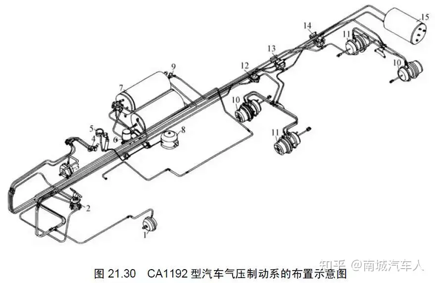
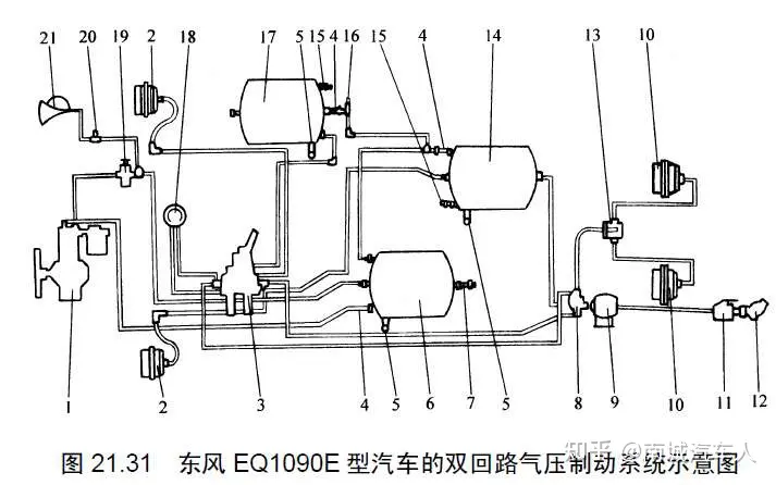
Introduction to the Vehicle Air Pressure Brake System and Air Circuit Principles
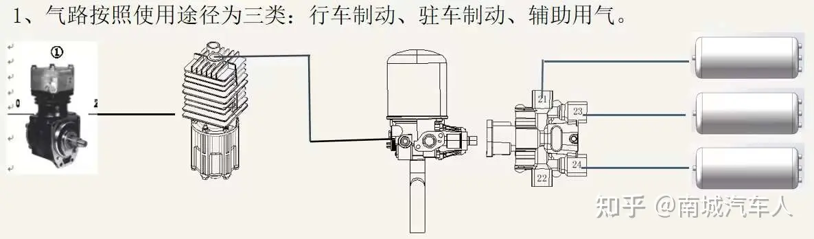
1. Pneumatic circuits are divided into three categories based on their usage:
Service brake, parking brake, and auxiliary air supply.
After the air compressor undergoes suction, compression, and pressurization, the final high-temperature air is delivered through a spiral steel pipe to the condenser. As the air passes through the condenser, the spiral structure inside causes contaminants such as water and oil to be thrown onto the inner wall of the valve body. These contaminants then flow along the inner wall towards the outlet, while the temperature of the compressed air is reduced. The air exiting the condenser reaches the dryer, where it is filtered and dried. The air coming out of the dryer then passes through a four-circuit protection valve and is divided into three routes, entering three sets of air reservoirs.
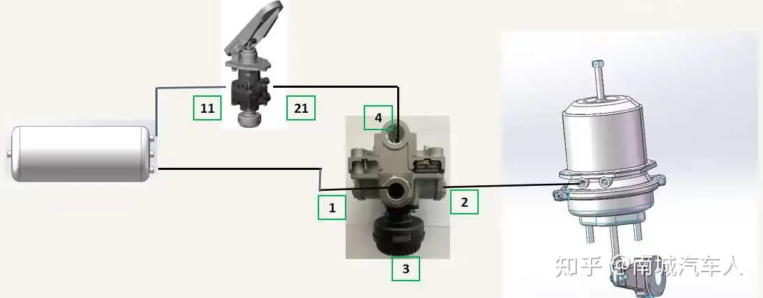
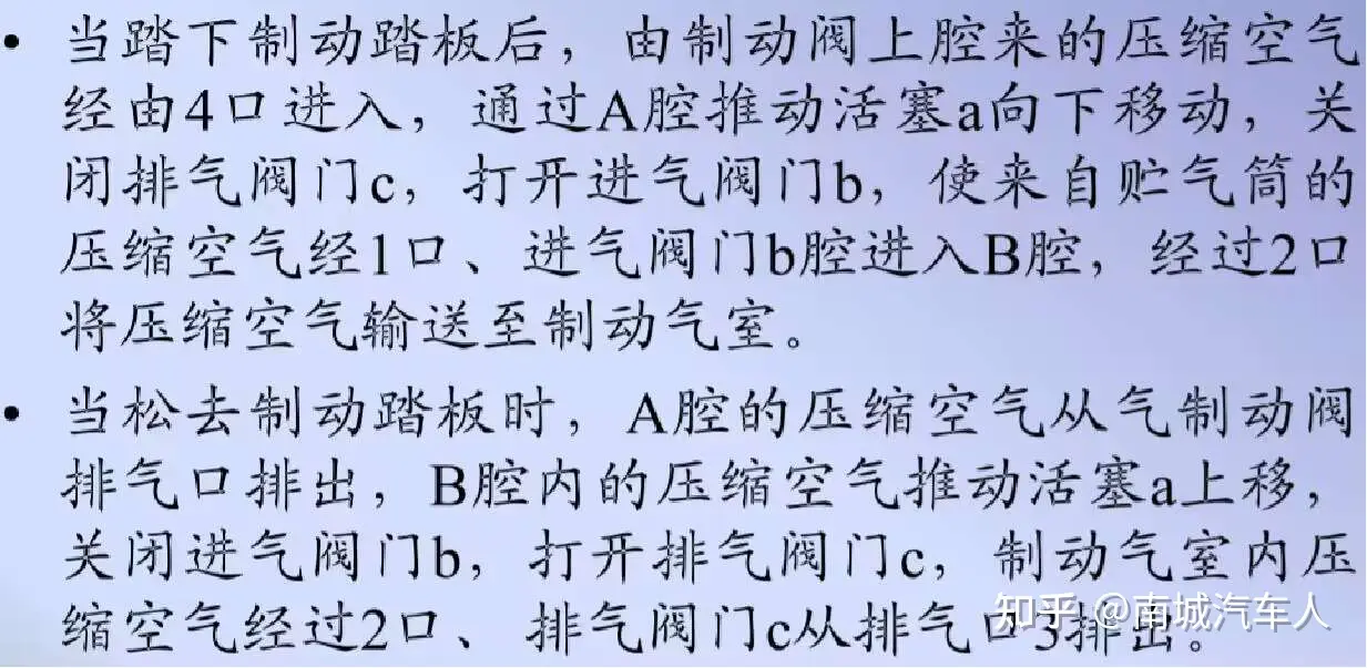
2. Vehicle Braking: Commonly known as the foot brake. It is controlled by the foot brake valve. When a person steps on the brake pedal, the force is transmitted to the foot brake valve. The foot brake valve opens the air circuit, allowing compressed air from the air reservoir to pass through the foot brake valve and reach port 4 of the relay valve. Port 4 is the control port of the relay valve. The gas enters port 4, pushing the piston to move, which opens the relay valve's air inlet port 1. The gas from the air reservoir enters through port 1 into the outlet port (port 2) of the relay valve, reaching the brake chamber. This pushes the piston in the brake chamber to move, which in turn drives the push rod, moves the adjusting arm, transmits the force to the brake lever, pushing the brake shoes outward. This causes the friction lining to contact the brake drum, producing friction and thus achieving braking.
3. Parking Brake: Also known as air cut-off brake, handbrake, or hand control valve. When the vehicle is in normal driving condition, the air circuit remains open, the intake port of the relay valve is in the open state, and the air from the storage tank passes through the relay valve's intake port to reach the brake chamber, thereby compressing the spring in the brake chamber via the diaphragm. The spring is compressed, and there is no braking effect. When parking brake is needed, the hand control valve is opened, and air passes through the hand control valve to reach port 4 of the handbrake relay valve. This pushes the diaphragm in the relay valve, closing the relay valve's intake port. The air in the brake chamber is exhausted through the exhaust port of the relay valve, and the compressed spring rebounds due to the absence of force, driving the movement of the push rod. This causes the adjustment arm at the lower end of the push rod to move, transmitting force to the brake lever, pushing the brake shoes outward so that the friction pads make contact with the brake drum, thereby achieving braking.
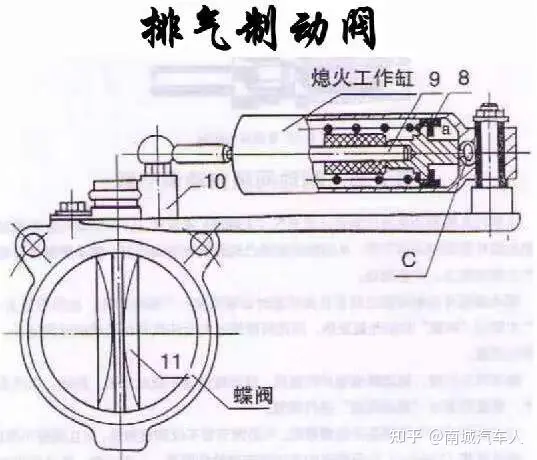
When the driver presses the exhaust brake switch, the solenoid valve controls the exhaust brake air circuit, causing the butterfly valve in the exhaust pipe to rotate and block the exhaust pipe. Compressed air enters the fuel cut-off cylinder as the button valve opens. Under the action of the compressed air, the piston in the fuel cut-off cylinder moves, and the push rod, through the linkage mechanism, drives the governor lever to stop the fuel supply, thereby preventing the engine from running and achieving the braking effect.
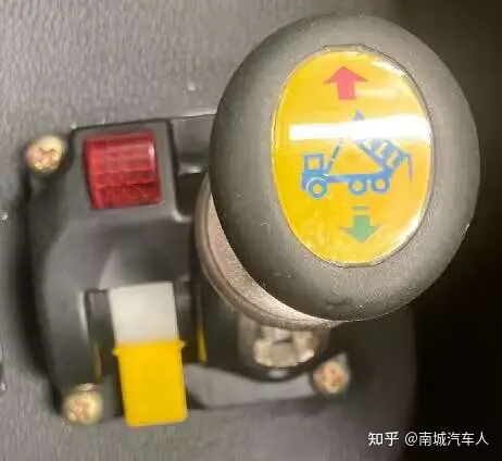
5. Auxiliary air usage: solenoid valve, air horn, lifting system, clutch booster.
2. Introduction to the Principles of Pneumatic Circuit Components1. Basic Pneumatic Circuit Connections1 — Air Inlet2 — Air Outlet3 — Exhaust Port4 — Control Port
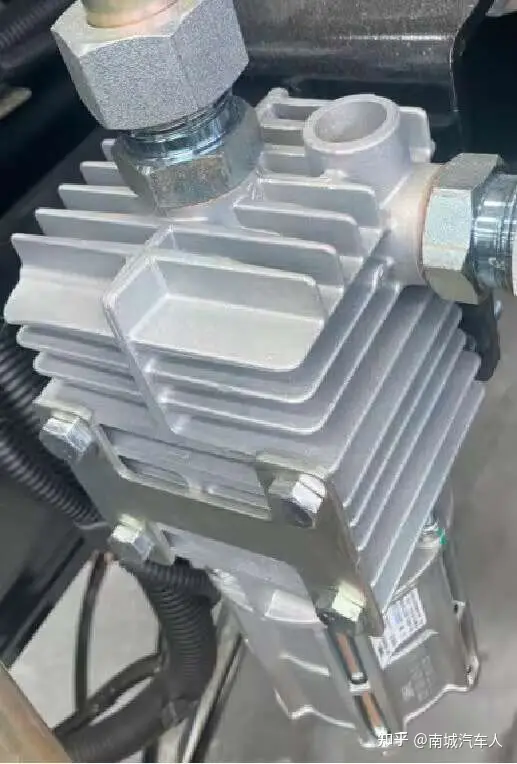
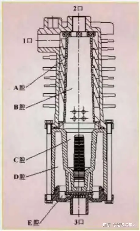
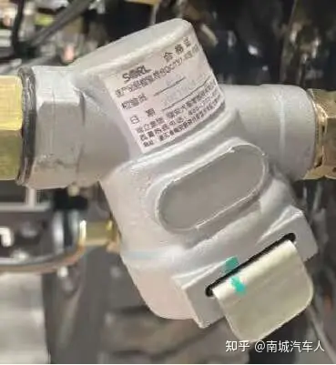
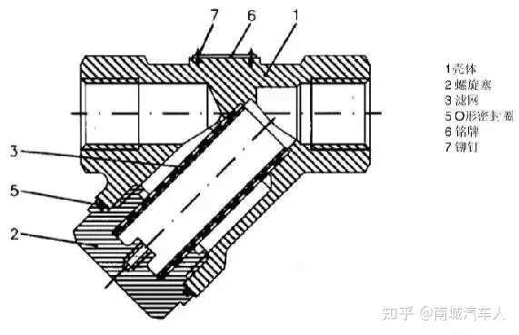
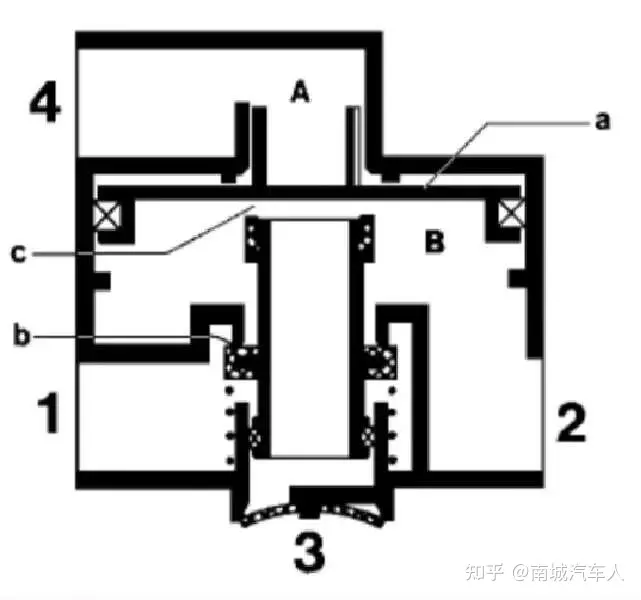
For example:11 — First air inlet12 — Second air inlet21 — First air outlet22 — Second air outlet2. Condenser1 — Air inlet2 — Air outlet3 — Exhaust and drainage outletInstalled between the air compressor and the dryer, it separates oil and water droplets from the flowing compressed air during the air compression process. The condensed substances are collected by a filter, separating the corresponding oil from the compressed air. Water and oil stored in the chamber are discharged from outlet 3.Heat is dissipated through the heat fins on the valve body, and water and oil are separated from the compressed air by centrifugal force in the spiral passage. As shown in the figure on the right, compressed air from the air compressor enters chamber A through port 1, flows into the spiral passage, where centrifugal force forces contaminants such as water and oil onto the valve body wall while lowering the air temperature. The contaminants flow along the wall, enter chamber C through small holes, pass through a filter rod and diaphragm, and enter chamber E. The compressed air, after removal of water and oil, enters chamber B and is output through the air outlet. When the dryer unloads, the pressure in chamber B drops. At this time, there is a pressure difference between chambers B and D, causing the diaphragm to lift, and the water and oil stored in chamber E are discharged from outlet 3.
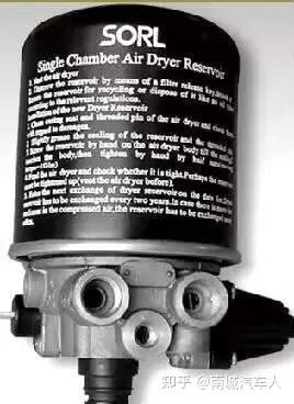
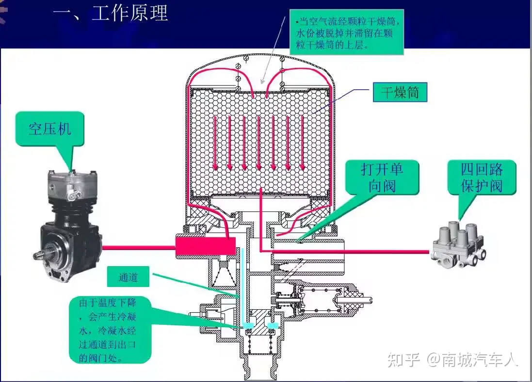
2. Condenser and Dryer1 — Air Inlet2 — Air OutletThe air dryer mainly dries the compressed air coming from the air compressor. When the temperature drops below 5°C, the heating rod starts working to heat the moisture in the air. The drying cylinder is the key component of the air dryer, continuously regenerating the desiccant molecular sieve to maintain uninterrupted drying. The sintered copper beads in the drying cylinder can filter tiny particles and dust, and the molecular sieve can dry the compressed air to 0.03 g/m³.Main functions of the dryer:1. Filter impurities in the gas.2. Absorb moisture in the gas.3. Regulate the pressure in the braking system.4. Provide heating to prevent freezing in low-temperature environments.5. Protect against pressure overload (1.3 MPa).
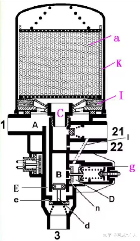
.Compressed air enters chamber A through port 1, passes through drying filter I and annular passage K to reach the upper part of the dryer. As the airflow passes through desiccant a, the moisture is adsorbed and retained on the surface of desiccant a. After flowing through passage C, a portion flows through port 22 to the air compressor to perform a cleaning function. Another portion flows through the one-way valve to port 21, while some compressed air enters chamber D through oblique hole 1, acting on the diaphragm assembly g. When the system air pressure exceeds the spring preload, g drives valve n to move to the right, opens valve n, allowing compressed air to enter chamber B, pushing piston d downward and opening exhaust valve e, thereby unloading the air compressor.
While the air compressor is unloading, the air from port 22 passes through passage C, desiccant a, annular passage K, drying filter I, passage E, and exhaust valve e to the exhaust port, thereby discharging the moisture adsorbed by desiccant a through the counterflow air.
When the pressure at port 21 drops by 60-130 KPa, due to the pressure decrease in chamber D, the diaphragm assembly g moves left, closing valve n. The compressed air in chamber B is discharged through small holes, and under the action of the spring, piston d moves upward to close exhaust valve e, restoring the air compressor supply to the system, and the entire drying process begins again.
Heater m prevents components such as valve e from freezing, thereby avoiding operational failures.
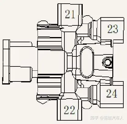
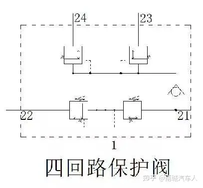
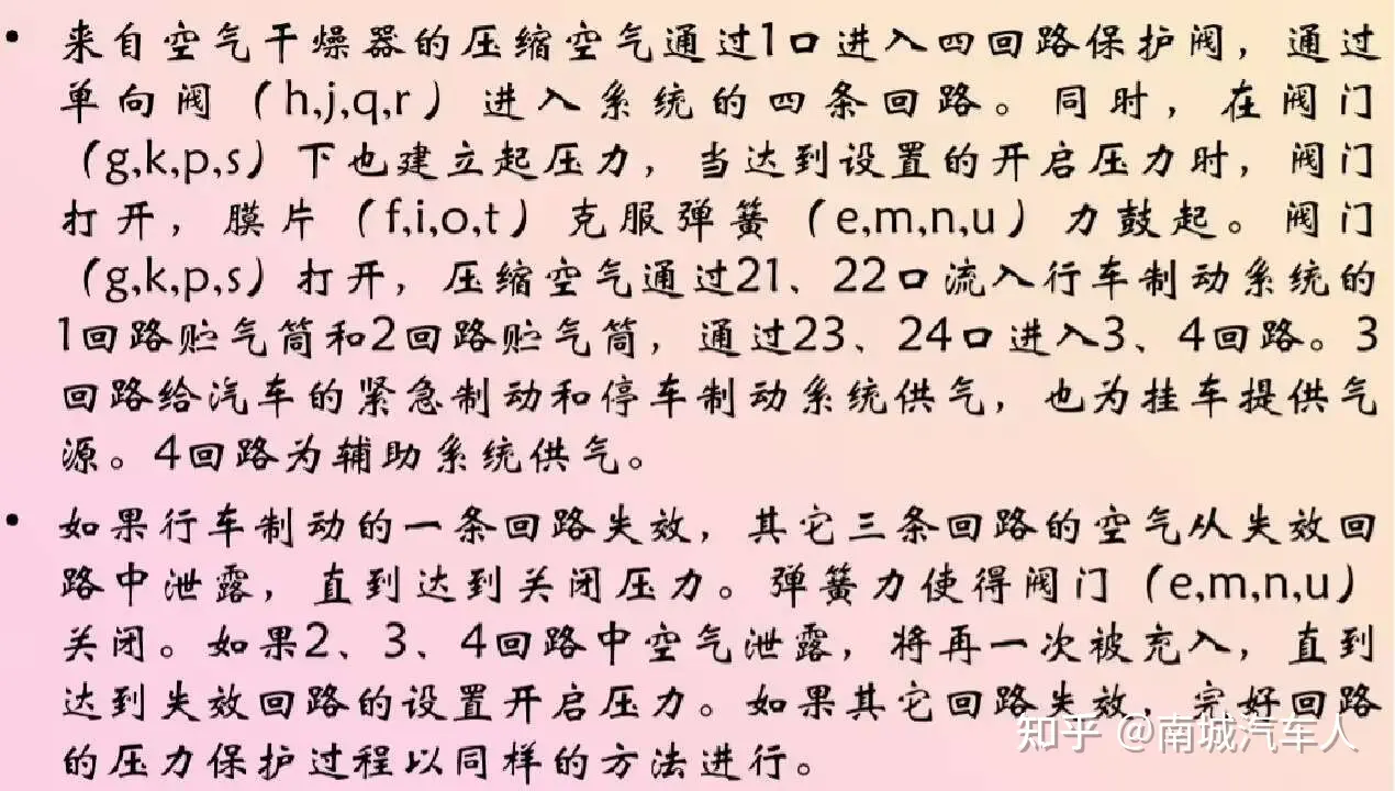
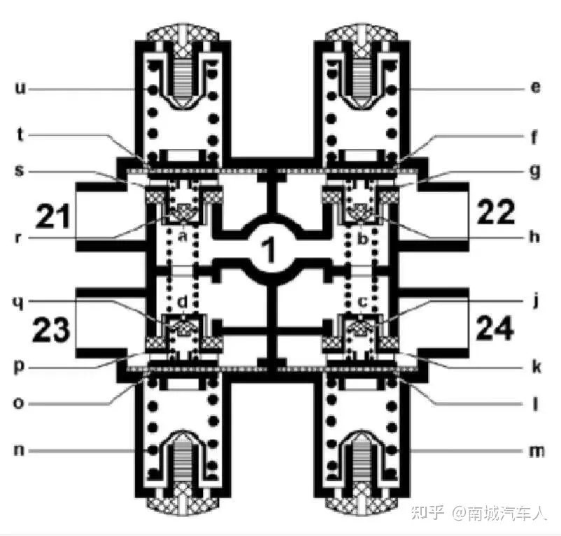
3. Four-Circuit Protection ValveUnder normal circumstances, the four-circuit protection valve functions like a five-way valve. When one circuit fails, for example if the first circuit fails, the pressure at outlet 2l continuously decreases due to leakage. Since all four valves are open at this time, gas from the remaining three circuits continuously supplements the first circuit, and the air pressure drops together. When it drops to a certain value, valve 1 closes under the action of the pressure-regulating spring, and the air pressure no longer decreases (this is the dynamic closing pressure). At this point, although the pressure at outlet 21 drops to zero due to leakage, the other three circuits can still maintain normal and safe braking pressure and continue to be replenished, greatly improving the safety of the vehicle.The three-circuit pipeline layout of on-site mine trucks:21 — Air reservoir — Upper chamber of the service brake master cylinder on the middle and rear axles, first circuit24 — Air reservoir — Lower chamber of the service brake master cylinder on the front axle, second circuit23 — Air reservoir — Exhaust valve and auxiliary air and parking brakeFunction of the four-circuit protection valve:The four-circuit protection valve has a protective closing pressure. After one circuit fails, the air pressure in the other circuits will not leak further once it drops to a certain pressure, and normal operation can still be maintained.
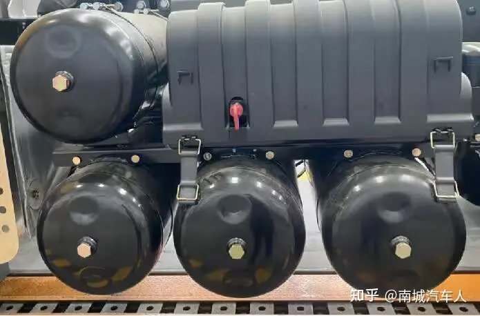
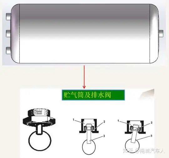
4. Air Reservoir1. Function of storing gas.2. Filtration function. Relatively heavy impurities such as moisture, oil, and dust in the air circuit will eventually fall to the bottom.3. Exhaust valve. The impurities that settle at the bottom can be released manually.4. Filter. Gas passes through the filter to remove any remaining oil and moisture.5. Pressure stabilization.6. Cooling.
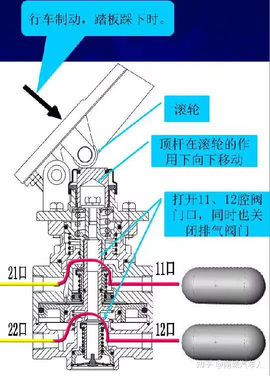
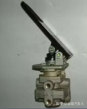
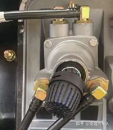
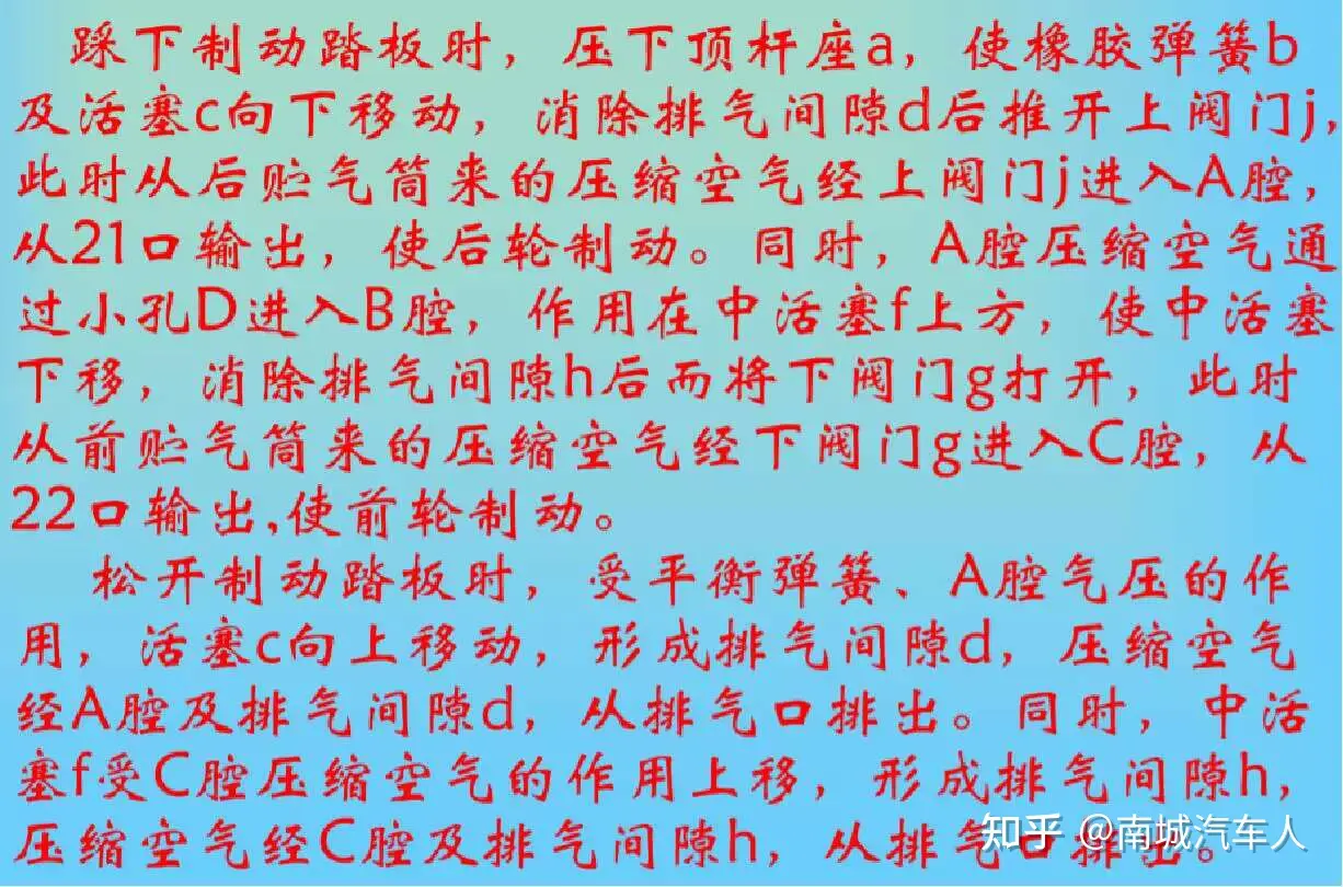
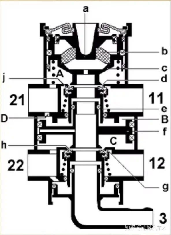
5. Foot Brake ValveDuring vehicle braking:When the main valve pedal is pressed, first open port 11, then open port 12, while simultaneously closing exhaust port 3. At this time, air flows from the air reservoir, passes through port 11 to reach port 21, then goes through the rear axle relay valve, reaching the brake chambers of the middle and rear axles to achieve braking of the two rear wheels. The air entering from port 12 passes through port 22 to reach the front axle relay valve, and through the front brake chambers, it applies braking to the front wheels.
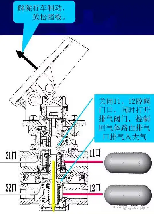
When releasing the vehicle brake:
Release the main valve pedal, and ports 21 and 22 of the main valve stop supplying air to the control port of the relay valve. The air in the brake chamber is discharged into the atmosphere through the connected relay valve.
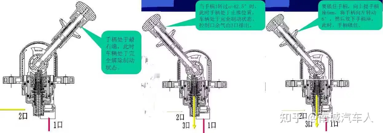
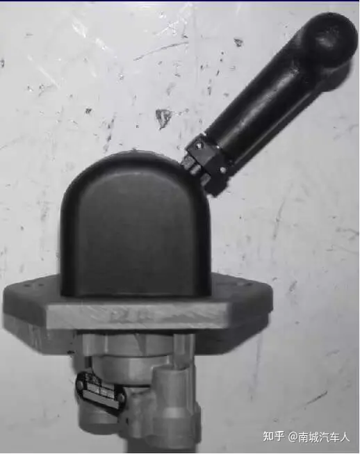
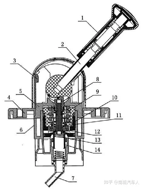
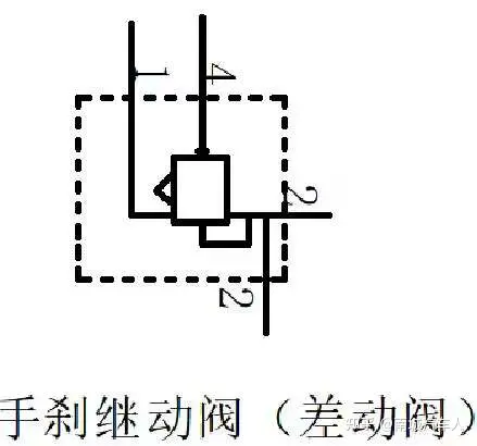
6. Manual Brake ValveParking brake, used to control the handbrake relay valve, thereby controlling the parking brake chamber in the brake air chamber.
When releasing the service brake:
Release the main valve pedal, and ports 21 and 22 of the main valve stop supplying air to the control port of the relay valve. The air in the brake chamber is expelled into the atmosphere through the connected relay valve.
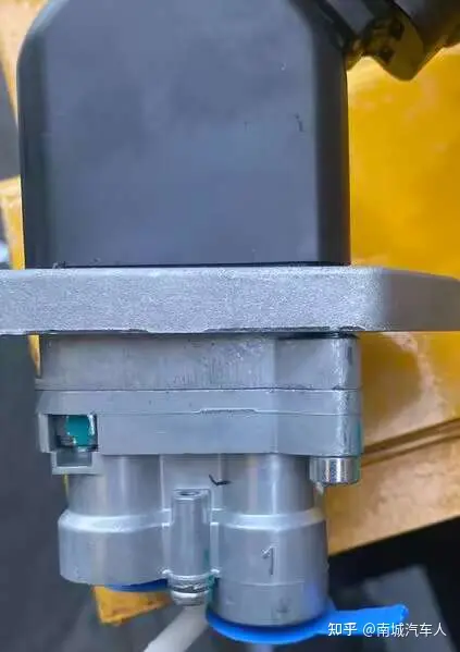
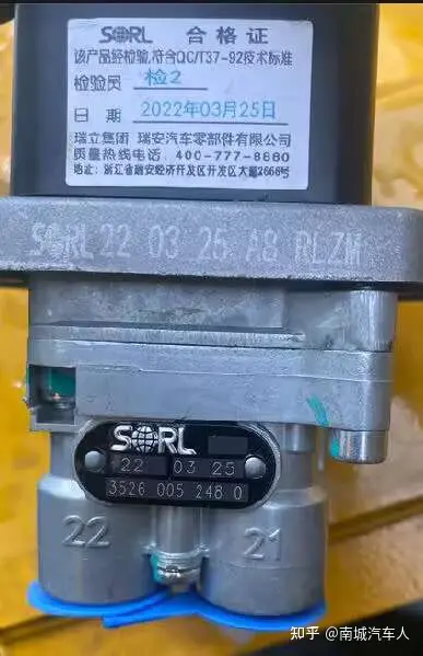
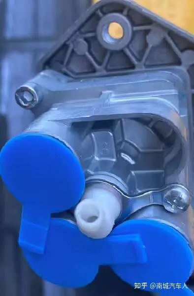
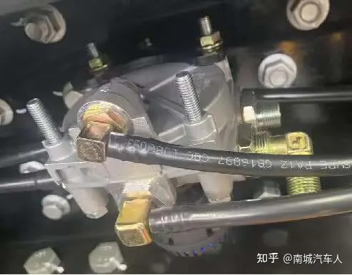
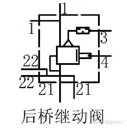
7. Front/Rear Relay Valve
1 — Inlet port
2 — Outlet port
3 — Exhaust port
4 — Control port
21 — First exhaust port
22——Second vent
The air coming from the foot brake valve enters the relay valve through port 4, pushing the diaphragm inside the relay valve downward. When the diaphragm moves downward, the rubber sealing pad moves downward together with the spring, opening the air passage. Compressed air from port 1 enters the valve chamber and reaches port 2, flowing into the brake air chamber. When the brake is released, the air from port 4 is cut off. The rubber sealing pad and spring rebound due to the absence of air pressure, pushing the diaphragm upward. The air from port 4 is then discharged through the pipeline from port 3 of the foot brake valve.
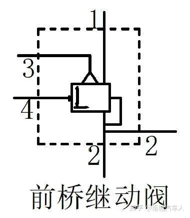
8. Front/Rear Relay Valve1 — Air Inlet2 — Air Outlet3 — Exhaust Port4 — Control Port21 — First Air Outlet22 — Second Air OutletThe handbrake relay valve operates on the same principle as the front and rear axle relay valves. The front and rear axle relay valves are normally closed, while the handbrake relay valve is normally open.
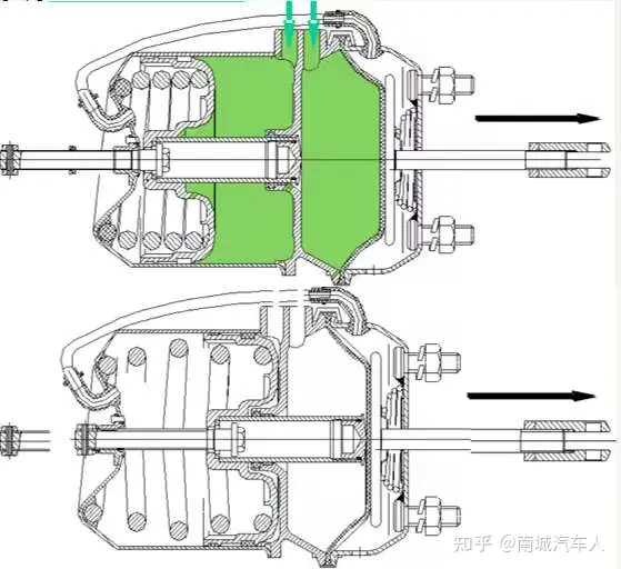
9. Brake Chamber — Service Braking30" — Service Brake Chamber36" — Parking Brake ChamberService Braking: Air from the relay valve enters the service brake chamber, pushing piston 5 to move to the right, which drives the push rod 2 to move to the right while compressing spring 4. The push rod 2 drives the movement of the adjustment arm on the axle, thereby achieving service braking.Releasing the Service Brake: When the foot brake valve stops supplying air, spring 4 rebounds backward due to the lack of pressure, driving the push rod to move to the left, which in turn drives the adjustment arm, thereby releasing the vehicle's brake.
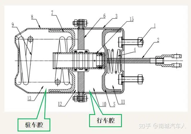
10. Brake Chamber — Parking BrakeParking Brake: During normal driving, there is a certain air pressure in the parking chamber, and the emergency brake spring is compressed. When the parking brake is applied, pulling down the handbrake causes the piston in the relay valve to block the air inlet and open the exhaust port. With no pressure acting on the spring, it moves to the right, and the air in the chamber is expelled through the exhaust port of the handbrake relay valve. The diaphragm moves to the right, simultaneously driving the push rod to the right, which in turn moves the adjusting arm, achieving the braking of the entire vehicle. Releasing the Driving Brake: Pulling the handbrake valve closes the air circuit. The diaphragm inside the brake valve rebounds because there is no pressure acting on it. At this point, the air path inside the relay valve opens, allowing air to flow into the brake chamber. The spring is compressed, and the push rod, under the action of the spring, drives the adjusting arm back, thereby releasing the brake of the entire vehicle.
Precautions:a. During installation, the product must be installed according to the schematic diagram. Be careful not to connect it incorrectly, otherwise air or oil leakage may occur. If air leakage occurs, promptly check whether all joints are tightened, and replace the sealing elements if necessary.b. The pipeline must be cleaned before assembly; otherwise, it will affect performance and service life.c. During installation, the pipeline should be arranged reasonably and aesthetically.For the entire pneumatic and hydraulic system, it is most important to understand its working principle, the function of each interface, and the working principle of key components.
Previous Page
Previous Page

Focus on the research and development of automotive brake systems and pneumatic brake valves to promote the development of the auto parts industry!
Contact Information
Telephone:86-575-87438928
Mobile:8613252110178
QQ:1185450863@qq.com
Address: No. 461, Advanced Village, Fengqiao Town, Zhuji, Zhejiang Province
Online message
Submit your information and we will contact you as soon as possible.