


20
2025
-
09
Extending the lifespan of the dryer: An interpretation of the Hande oil-water separator
With the development and progress of the domestic automotive industry, vehicle safety has received increasing attention from society. At the national level, following the release of passenger car brake system standards, the National Standardization Management Committee issued GB12676-2014 "Technical Requirements and Test Methods for Brake Systems of Commercial Vehicles and Trailers" on October 10, 2014, which outlines the overall framework for designing vehicle brake systems for automotive industry practitioners from the perspective of laws and regulations.

As we all know, in the current domestic commercial vehicle sector, the majority of braking systems are pneumatic braking systems. Whether it is a separate air compressor system used for purely electric vehicles or the air compressor system in conventional vehicles, during operation, it inevitably brings some mixture of oil and water as well as impurities into the subsequent braking system to some extent; especially for vehicles using conventional internal combustion engines, some of the engine oil contaminants will be brought into the subsequent pipelines during operation.Excessive mixtures of oil and water and impurities can cause air leakage or jamming in the braking system components, corrosion and blockage in the pipelines, leading to abnormal operation of the components, affecting the performance of the braking system and potentially leading to vehicle safety issues. The good performance of the braking system relies on each component of the braking system. Any component failure or abnormal operation can greatly reduce the performance of the braking system, leading to safety hazards in vehicle braking.Providing clean compressed air for the braking system can effectively ensure the normal operation of braking system components. Currently, the dryers configured for braking systems in the market can filter the water vapor from compressed air, but they are nearly ineffective in separating oil mist. Furthermore, the application environment for domestic commercial vehicles is not standardized, and maintenance of dryers is infrequent; if the drying tank is not replaced for a long time, it can easily result in the flow of oil-water mixtures and impurities into the subsequent system, leading to abnormal conditions in braking components. Based on this situation, oil-water separators, as efficient filtering devices for oil-water mixtures and impurities, are gradually being widely applied in domestic commercial vehicles.● Function of Oil-Water SeparatorOil-water separators, also known as condensers, are referred to as "compressed air oil-water separators" by some manufacturers. The oil-water separator is the first line of defense to ensure the cleanliness of compressed air in the braking system. Under extreme operating conditions, the oil-water mixture and impurities in the system can severely affect the performance of the braking system and the lifespan of its components. The oil-water separator is usually installed between the air compressor and the air dryer, requiring very little maintenance during long-term use.When properly matched, the oil-water separator can filter (separate) up to 90% of the oil-water mixture and impurities, and the maintenance cycle (or lifespan) of the dryer can be extended by at least three times. A reasonable match of the oil-water separator and dryer can provide clean compressed air for the braking system, thereby ensuring stable and reliable performance of the braking system.● Working Principle of the Oil-Water SeparatorIn 1989, HALDEX launched the first electronically controlled oil-water separator (Figure 1 left). In 2010, HALDEX introduced the air-controlled oil-water separator (Figure 1 right). The former is mature and stable, while the latter features a simple structure and high cost-performance ratio. Currently, these two types of oil-water separators are widely used in the domestic market; the former is mainly used in buses, while the latter is primarily used in trucks.
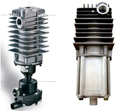
Figure 1: Electric control and air control oil-water separatorThe oil-water separator consists of two parts: the upper part is mainly responsible for the separation of the oil-water mixture and impurities; the lower part is mainly responsible for discharging the oil-water mixture and impurities from the oil-water separator. The lower part features an electric control automatic drainage valve or an air control automatic drainage valve.The working principle of the oil-water separator is shown in Figure 2. Compressed air flows into the spiral pipeline through the intake port on the side. Inside the oil-water separator, compressed air flows in a downward spiral space, and under the influence of centrifugal force, it leaves the oil-water mixture and impurities on the deflector. After reaching the bottom of the spiral track, the compressed air will flow out from an upward vertical channel and through the outlet at the top. At the same time, the oil-water mixture and impurities condensed on the deflector will flow into the bottom collector under the force of gravity.
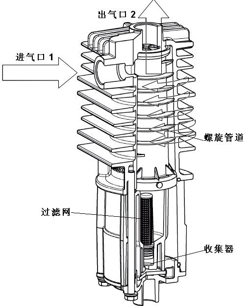
Figure 2 Oil-water separatorFor the electric control oil-water separator, its lower part consists of an electrically controlled automatic drainage valve. When the drainage valve is activated by electricity, the oil-water mixture and impurities in the bottom collector will be discharged. The electric control automatic drainage valve is generally controlled by a timer relay or brake light. For the pneumatic control oil-water separator, its lower part consists of a pneumatic control automatic drainage valve, as shown in Figure 3.
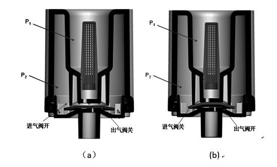
图3 气控自动放水阀
When the oil-water separator is supplying gas to the brake system under pressure, as shown in figure (a), the air pressure at the oil-water separator (p1) increases, thereby opening the intake valve diaphragm. Compressed air will pass through the intake valve and be stored in the collection chamber of the oil-water separator (p2) until the pressure is balanced on both sides of the diaphragm; at this point, the intake valve diaphragm will close.When the unloading valve of the air dryer is opened, it reduces the air pressure between the air compressor and the dryer, causing the exhaust valve diaphragm to open, as shown in figure (b). The oil-water mixture and impurities are expelled through the exhaust valve into the atmosphere or flow into an external collection tank. When the pressure in the collection chamber of the oil-water separator (p2) decreases to a certain level, the diaphragm closes. ● Requirements for oil-water separator matchingThe installation bracket of the oil-water separator must have sufficient strength to avoid damage to pipe connections and valve bodies due to vehicle vibrations. The oil-water separator needs to be installed in a location with enough space for installation service that is also convenient for periodic inspections and well-ventilated. Additionally, it should be located away from the wheel area to avoid contamination of the valve body from tire splashes and to prevent damage to the oil-water separator (including brackets, lines, and joints) caused by minor external impacts on the vehicle.
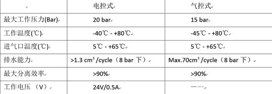
The discharge ports of the oil-water separator and the automatic drain valve must be installed vertically downwards, with an inclination angle not exceeding 15°. The surrounding heat sources should be relatively small, and the ambient temperature should ideally be between -40°C and 80°C. The installation position should be as close as possible to the air dryer to achieve optimal separation and discharge effects.To prevent moisture accumulation, the pipeline from the air compressor to the oil-water separator needs to have a certain continuous slope, and the inner diameter of the connection points between different pipelines must not be less than 1/2 of the inner diameter of the connecting pipes. Otherwise, it is required to extend a section of the connecting pipe vertically upwards from the air compressor outlet to form a slope to the oil-water separator.A similar sloped incline is also required from the oil-water separator to the dryer. The design and selection of materials, lengths, and dimensions for the connecting pipes from the air compressor to the oil-water separator should ensure that the compressed air temperature reaching the oil-water separator is between 5°C and 65°C. It is important to avoid too low an intake temperature, as this may cause condensation to freeze in the pipeline or at the air intake of the oil-water separator in cold environments; similarly, avoid too high an intake temperature, as this may damage the sealing components of the oil-water separator or the automatic drain valve, thus reducing the separation and discharge effectiveness of the oil-water separator.The pipelines of the air compressor should not significantly obstruct the flow of internal air, as this could increase the possibility of ice formation in the pipes. Additionally, the use of 90° elbows should be minimized.Main technical parameters.
● Maintenance and Care of Oil-Water SeparatorsThe maintenance intervals for oil-water separators are mainly determined by the working environment in which they are used. If any abnormal operation of the product is detected during vehicle testing or operation, immediate inspection and necessary repairs are required. After disassembly for maintenance, it is crucial to check if the product functions normally and whether there are any air leaks. If it is found that the recommended maintenance cycle is too long or too short during actual use, users can adjust it according to their specific situation.Generally recommended maintenance cycles are as follows: City buses: 1 year or 50,000 kilometers; Urban buses and trucks: 1 to 2 years.For issues like air leaks caused by carbon build-up or oil contamination, the aluminum casing of the oil-water separator needs to be cleaned regularly, while other components can be cleaned or replaced based on actual conditions. The automatic drainage valve's filter screen, valve core, O-ring seal, and gaskets need to be cleaned or replaced as required.● Common Failures of Oil-Water Separators
In the aftermarket of oil-water separators, the main failure mode is air leakage from the exhaust port. This is mainly due to long-term lack of maintenance, leading to excessive accumulation of oil-water mixtures and impurities, which causes wear on the automatic drainage valve core (electric control), exhaust diaphragm (pneumatic control), and sealing components resulting in air leakage; or during winter, the accumulated oil-water mixtures and impurities freeze, causing the valve core or exhaust diaphragm to become stuck, leading to air leakage.For situations with a lack of maintenance, users must perform timely maintenance according to installation requirements. Proper matching and usage, as well as reasonable maintenance, are essential to ensure the normal operation of the oil-water separator.For faults caused by freezing in winter, the focus is mainly on the application market of electric control oil-water separators in the central and northern regions of the country. The author recommends performing maintenance on vehicle oil-water separators before the arrival of winter to remove any potentially accumulated oil-water mixtures and impurities. Moreover, the following methods can be employed to help avoid air leakage issues caused by winter freezing.
Using a heater to heat the automatic drainage valve of the oil-water separator. Generally, there are two designs, using the coil of the automatic drainage valve body and an additional coil for heating. I do not recommend the additional coil heating due to its complex structure and the safety hazard of overheating which can lead to wire burning. After testing, it has been found that by continuously supplying power to the body coil, the coil itself can be used as a heating element to heat up, enduring continuous heating for 72 hours at room temperature (20℃); the coil power ranges from 12 to 15 watts, and in a -40℃ environment mimicking the air compressor's operation in vehicles, it can heat the automatic drainage valve to above 0℃ within 6 minutes, which meets the end user's requirements.Using a time relay for the interval drainage control of the automatic drainage valve. The electrically controlled oil-water separator is generally set to use the brake signal, performing drainage each time the brakes are applied. For long-distance trucks and buses with fewer braking instances, a long period without braking can lead to an excess buildup of oil-water mixtures and impurities, causing ice formation and leaks. The time relay-controlled solution can effectively increase the number of drainage instances to eliminate oil-water mixtures and impurities, avoiding ice formation and leaks.● Summary
The quality of air compressor products in the market is uneven, and there is a significant issue with oil leakage. Before matching with oil-water separators, the high compensation claims for dryers are commonly seen among major domestic manufacturers. This situation indirectly corroborates that components of the braking system are likely operating in harsh environments containing oil-water mixtures and impurities, posing certain safety risks for vehicle braking. In the European market, oil-water separators began to be used in commercial vehicles in 1989, and to date, they have been widely adopted by leading brands such as Volvo, Mercedes, MAN, and Iveco.Major domestic manufacturers of trucks and buses are also increasingly focusing on and equipping oil-water separators. For Euro IV models, many manufacturers have made oil-water separators standard. Currently, the configuration rate of oil-water separators in heavy and medium commercial vehicles in China is only about 5%. As a highly efficient and cost-effective product, I believe that in the coming years, the configuration rate of oil-water separators will see a significant increase.
Previous Page
Next Page
Previous Page
Next Page

Focus on the research and development of automotive brake systems and pneumatic brake valves to promote the development of the auto parts industry!
Contact Information
Telephone:86-575-87438928
Mobile:8613252110178
QQ:1185450863@qq.com
Address: No. 461, Advanced Village, Fengqiao Town, Zhuji, Zhejiang Province
Online message
Submit your information and we will contact you as soon as possible.