


16
2025
-
09
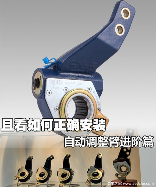
Let's see how to correctly install the advanced automatic adjustment arm.
In the comments of the article about the automatic adjusting arm tutorial, some users hope to understand the installation process of the automatic adjusting arm. Considering the versatility of the installation methods we provided, we will only present the installation method for the Longzhong II generation automatic adjusting arm, which has a relatively high market share. Additionally, we will also cover the disassembly and maintenance methods of the automatic adjusting arm, and finally, we will provide common problems and solutions for the Longzhong automatic adjusting arm, hoping to be helpful to users.
Installation Method One: (Applicable for customers who install the automatic adjustment arm before the air chamber)
图一
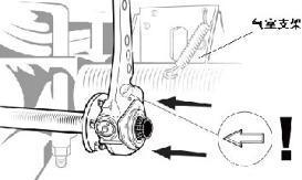
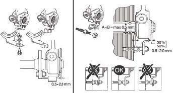
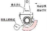
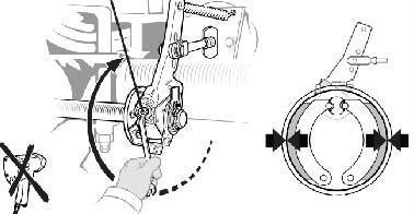
1. Install the automatic adjustment arm on the camshaft. Note that the direction of the arrow on the housing should be consistent with the braking direction, which means that the push rod of the brake air chamber should push the automatic adjustment arm outward. The handle of the automatic adjustment arm housing should be kept as far away from the air chamber support as possible to prevent interference during the subsequent installation of the air chamber (see Figure 1).

图二

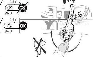
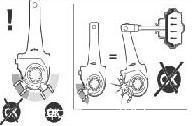
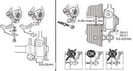
Figure 3Push the control arm towards the braking direction (the control arm has an arrow indicating the pushing direction) as far as possible to the bottom end, ensuring that the automatic adjusting arm's control arm is secured. After the automatic adjusting arm is installed, the control arm should be within the shaded area shown in the figure, with a label on the cover plate (see Figure 2). Otherwise, there will be an interference phenomenon between the control arm and the housing during braking (see Figure 3).2. Use spacers, screws or washers, and snap rings to secure the automatic adjusting arm onto the camshaft, ensuring that the axial clearance of the automatic adjusting arm is 0.50-2.00mm.
图四
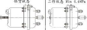
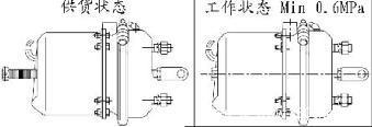
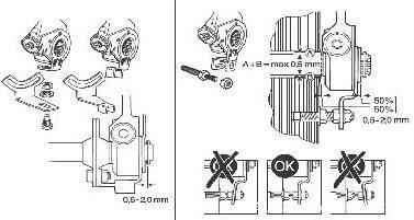
3. Install the air chamber according to the instructions provided by the manufacturer of the brake air chamber, ensuring that the push rod of the brake air chamber is in the initial position. For the spring parking brake air chamber, the air chamber should be in the supply state (i.e., the screw is screwed out of the air chamber), or the screw can be screwed into the air chamber to bring the air chamber into working state, then inflate the air chamber to maintain the air pressure above 0.6MPa so that the push rod of the air chamber is in the initial position (see Figure 4).
图五
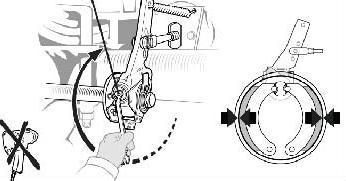
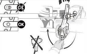
4. Use a SW12 wrench to rotate the worm hexagon head at the end of the automatic adjustment arm clockwise (Note: Do not use electric wrenches or pneumatic drills), so that the hole of the automatic adjustment arm aligns naturally with the positioning hole of the sub-pump push rod U-shaped fork, and then easily insert the cylindrical pin into the U-shaped fork hole and lock it with a cotter pin (see Figure 5).
图六
5. Install the bracket for the automatic adjusting arm to secure the control arm onto the bracket (see Figure 6).
图七

图八
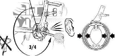
6. Use a wrench to turn the hex head of the automatic adjusting arm worm gear clockwise until the friction plate contacts the brake drum, then turn the hex head of the worm gear counterclockwise for 3/4 of a turn (you will hear a clicking sound when turning in reverse) (see Figure 7, Figure 8). Note: Do not use an electric wrench or pneumatic drill!7. Apply the brakes several times, and the brake gap will automatically adjust to the normal range. The adjustment function can be observed as the hex head of the worm gear rotates clockwise automatically when the braking is about to end, thus completing the installation process. Installation method two: (suitable for customers who install the air chamber first before installing the automatic adjusting arm)
图九
1. Install the air chamber according to the instructions provided by the manufacturer of the brake air chamber, ensuring that the push rod of the brake air chamber is in the initial position. For the spring parking brake air chamber, the air chamber should be in the supply state (i.e., the screw is screwed out of the air chamber), or the screw can be screwed into the air chamber to bring it into working state and then inflate the air chamber to maintain air pressure above 0.6Mpa, so that the push rod of the air chamber is in the initial position (see Figure 9).
图十
图十一
图十二
2. Install the automatic adjusting arm onto the camshaft. Note that the direction of the arrow on the housing should align with the direction of braking, meaning that the direction in which the brake chamber push rod pushes the automatic adjusting arm (see Figure 10). Push the control arm towards the braking direction (the control arm has an arrow indicating the pushing direction) as far as possible to the end, and ensure that the control arm of the automatic adjusting arm is not fixed. When the automatic adjusting arm is installed, the control arm should be within the shaded area shown in the figure, with markings on the cover plate (see Figure 11); otherwise, there will be interference between the control arm and the housing during braking (see Figure 12).
图十三
3. Use a SW12 wrench to rotate the worm gear hexagon head at the end of the automatic adjustment arm clockwise (Note: Electric wrenches and pneumatic drills cannot be used) to naturally align the hole of the automatic adjustment arm with the positioning hole of the sub-pump push rod U-shaped fork, then easily insert the cylindrical pin into the U-shaped fork hole, and lock it with a retaining pin (see Figure 13). 4. Fix the automatic adjustment arm to the camshaft with a spacer, bolts or washers, and retaining rings. At this time, it should be ensured that the axial clearance of the automatic adjustment arm is 0.50-2.00mm.
图十四
5. Install the bracket for the automatic adjusting arm and secure the control arm to the bracket (see Figure 14).
图十五
图十六
6. Use a wrench to turn the automatic adjustment arm worm gear hex head clockwise until the friction plate contacts the brake drum, then turn the worm gear hex head counterclockwise for 3/4 of a circle (you will hear a clicking sound during the reverse rotation) (see Figure 15, Figure 16). Note: Do not use an electric wrench or pneumatic drill!7. Apply brakes several times; the brake clearance will automatically adjust to the normal range. The adjustment function can be observed by the automatic rotation of the worm gear hex head clockwise as the braking is about to end. Thus, the installation process is complete. II. Disassembly Steps for the Automatic Adjustment Arm1. Remove the cotter pin and cylindrical pin connecting to the brake caliper to separate the brake caliper from the automatic adjustment arm.2. Remove the axial positioning ring and bolt (or washer and snap ring) from the upper end of the camshaft.3. Use an SW12 wrench to turn the worm gear hexagon head counterclockwise (the torque required is quite large, and you will hear a clicking sound) until the handle part of the automatic adjustment arm disengages from the U-shaped fork of the caliper push rod.4. Remove the support bolts, nuts, and washers connecting the control arm to the positioning support. Finally, take the automatic adjustment arm out of the camshaft.III. Maintenance of the Automatic Adjustment Arm1. Add lithium-based grease to the automatic adjustment arm every 20,000 kilometers.
图十七
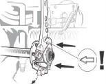
2. For every 20,000 kilometers, turn the worm gear hex head of the automatic adjustment arm counterclockwise and measure whether the torque exceeds 18 N.m. Repeat the measurement three times. If the measured torque is less than 18 N.m, it indicates that the automatic adjustment arm is damaged and the entire assembly must be replaced promptly (see Figure 17).4. Possible Installation ErrorsError 1: When the U-shaped fork pin hole of the air chamber push rod is not aligned with the hole at the handle of the automatic adjustment arm, attempting to forcefully insert the cylindrical pin. Correction method: Rotate the worm gear hex head clockwise or counterclockwise until the hole at the handle of the automatic adjustment arm naturally aligns with the pin hole of the U-shaped fork, then easily insert the cylindrical pin into the U-shaped fork hole and secure it with a cotter pin. During installation, if the air chamber push rod is too long, the U-shaped fork blocks the automatic adjustment arm, you can rotate the U-shaped fork back a certain distance.Error 2: Frequently using a wrench to tighten the worm gear hex head. Correction method: Due to the structural characteristics of the automatic adjustment arm, its clearance is automatically adjusted, so it is required that the worm gear hex head should only be rotated during installation, disassembly, or inspection; otherwise, it will severely affect the product's lifespan.
Previous Page
Previous Page

Focus on the research and development of automotive brake systems and pneumatic brake valves to promote the development of the auto parts industry!
Contact Information
Telephone:86-575-87438928
Mobile:8613252110178
QQ:1185450863@qq.com
Address: No. 461, Advanced Village, Fengqiao Town, Zhuji, Zhejiang Province
Online message
Submit your information and we will contact you as soon as possible.